Everything you need for a first-time PathFinder setup, on one page — download, connect, tune and calibrate, in order. For an explanation of individual functions and parameters, see the Reference & Parameters page instead.
Download — PathFinder Configuration Tool
This is the only download you need to get started. The regular PathFinder app (Client) is for day-to-day use later — not needed yet.
The PathFinder Configuration Tool is the Windows application used to connect to, configure,
calibrate and update the PathFinder interface. Includes avrdude for firmware updates.
Connect to PC
Plug in the USB interface, connect the rotor clock, and make the first connection with the Configuration Tool.
Connect the interface via USB
Plug the USB-B cable into the PathFinder interface and a free USB port on your PC. Windows automatically installs the FT232RL driver. A new COM port appears in Device Manager (e.g. COM7).
Connect the rotor clock
Connect the Mini-DIN-6 (or DIN-8) cable from the PathFinder interface to the corresponding port on your DX(A/C) rotor clock. Make sure the rotor clock is powered on.
Open the Configuration Tool and connect
Launch the PathFinder Configuration Tool. Select the correct COM port from the dropdown (e.g. COM7) and click Connect. The firmware version confirms a successful connection.
Read current parameters
Click Read Parameters. All stored values — protocol, modes, speeds, offsets and calibration ADC values — are loaded into the UI.
Tuner — ADC Tuner
Adjust the potentiometer voltage so the ADC input is in the correct range — before running the calibration wizard.
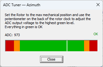
PathFinder reads the rotor position via an analogue voltage from the potentiometer in the rotor clock. This voltage must be within the safe working range of the interface's 10-bit ADC (0–5 V). The built-in ADC Tuner shows the live ADC value with a colour-coded bar — no multimeter needed.
How to tune
Open the ADC Tuner via the Settings menu in the PathFinder Configuration Tool. There is a separate tuner window for each axis (AZ and EL).
- Drive the rotor to its mechanical end stop (fully clockwise for AZ, fully up for EL).
- The ADC value and colour bar update in real time.
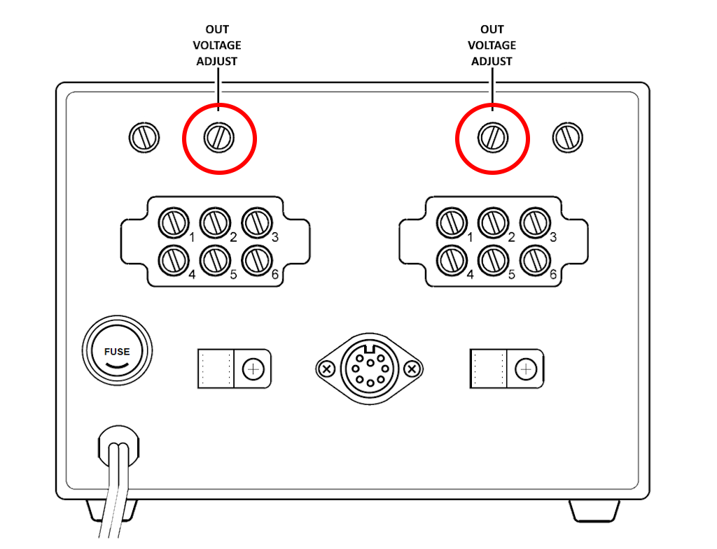
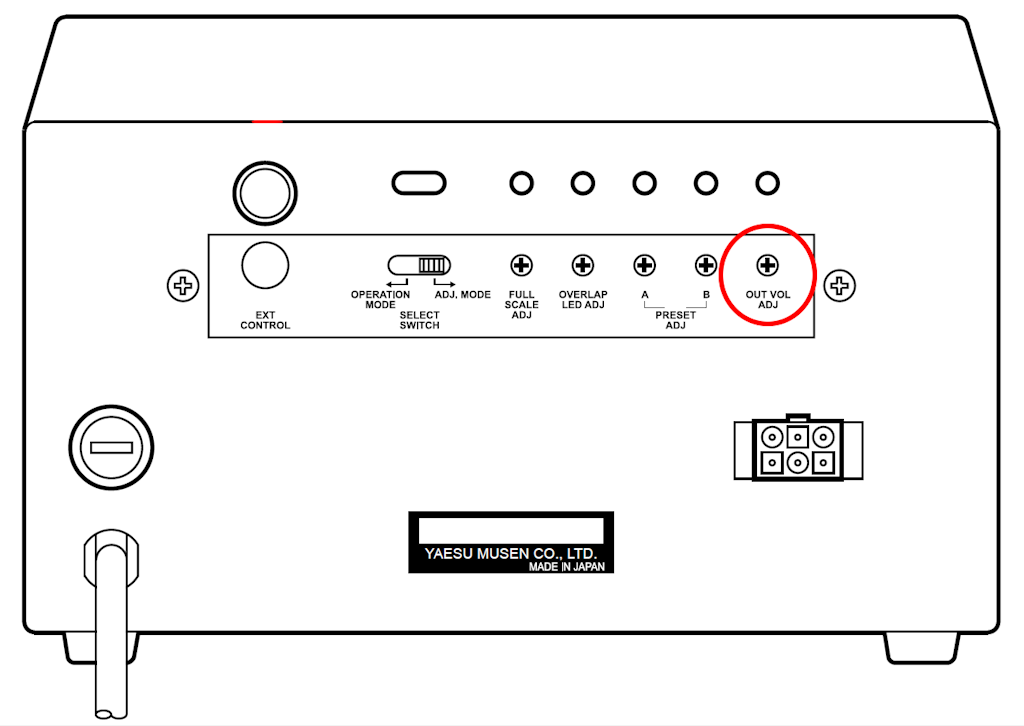
- Using a small screwdriver, adjust the trimmer on the back of the rotor clock until the bar sits firmly in the green zone.
- When OK is displayed, the voltage is correctly set.
- Repeat for the other axis if needed.
Trimmer location — by rotor clock model
The output voltage trimmer is located on the back panel of the rotor clock. The position differs per model:
Calibrate — Anchor Points
Drive the rotor to known reference angles and capture the ADC value at each point.
How calibration works
PathFinder reads the rotor position from a potentiometer connected to the DX rotor clock. The potentiometer supplies an analogue voltage that the interface's 10-bit ADC converts to a value between 0 and 1023. Because potentiometers are not perfectly linear, PathFinder uses multi-point calibration: you drive the rotor to known reference angles and capture the ADC value at each point. The firmware then interpolates between these anchor points to calculate the actual angle for any intermediate position.
Why multi-point?
A simple linear mapping (min/max) cannot compensate for potentiometer non-linearity or mechanical coupling error. With 5 anchor points (0°, 90°, 180°, 270°, 360°) PathFinder fits a piecewise-linear curve through all points, achieving better than ±2° accuracy across the full range — even with a 5–10% non-linear potentiometer.
| Axis | Anchor points | Angles | Modes |
|---|---|---|---|
| Azimuth | CA1 – CA5 (or CA6) | 0°, 90°, 180°, 270°, 360° (+ 450° in Mode 2) | Mode 1 = 0–360° · Mode 2 = 0–450° |
| Elevation | CE1 – CE2 (or CE3) | 0°, 90° (+ 180° in Mode 2) | Mode 1 = 0–90° · Mode 2 = 0–180° |
Azimuth calibration
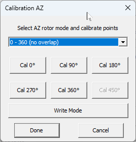
Open the Calibration AZ dialog by clicking Calibrate in the Calibration Azimuth group in the main window.
Select the rotor mode
Choose 0 – 360 (no overlap) for standard rotors, or 0 – 450 for rotors with an extended overlap zone (e.g. G-2800). The Cal 450° button is only enabled in 0–450° mode.
Drive the rotor to 0° (North)
Use the manual control on the rotor clock to rotate the antenna precisely to North (0°). Use a compass or known bearing as reference. Then click Cal 0°. PathFinder captures the current ADC value.
Drive to 90° (East) → Cal 90°
Rotate to East. Wait until the rotor has fully stopped, then click Cal 90°.
Drive to 180° (South) → Cal 180°
Rotate to South. Click Cal 180°.
Drive to 270° (West) → Cal 270°
Rotate to West. Click Cal 270°.
Drive to 360° (North again) → Cal 360°
Rotate back to North (full revolution). Click Cal 360°. For 0–450° mode, continue to 450° and click Cal 450°.
Elevation calibration
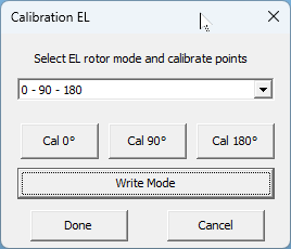
Click Calibrate in the Calibration Elevation group in the main window.
Select the elevation mode
Choose 0 – 90 for standard LEO satellite tracking. Choose 0 – 90 – 180 for EME or over-zenith satellite tracking (CE3 is only available in this mode).
Drive to 0° (horizon) → Cal 0°
Lower the elevation rotor fully to horizontal (0°). Use a spirit level on the boom if available. Click Cal 0°.
Drive to 90° (zenith) → Cal 90°
Bring the elevation rotor to vertical (pointing straight up). Click Cal 90°.
(0–180° mode only) Drive to 180° → Cal 180°
Continue past zenith to 180° (pointing back down on the other side). Click Cal 180°.