Reference documentation for every PathFinder function and parameter. First-time setup? Use the Installation workflow instead — it walks through download, connect, tune and calibrate in order.
Application Overview
The PathFinder Configuration Tool is the Windows application used to connect to, configure, calibrate and update the PathFinder interface. All settings are stored in the interface's EEPROM, so they survive power cycles and firmware updates.
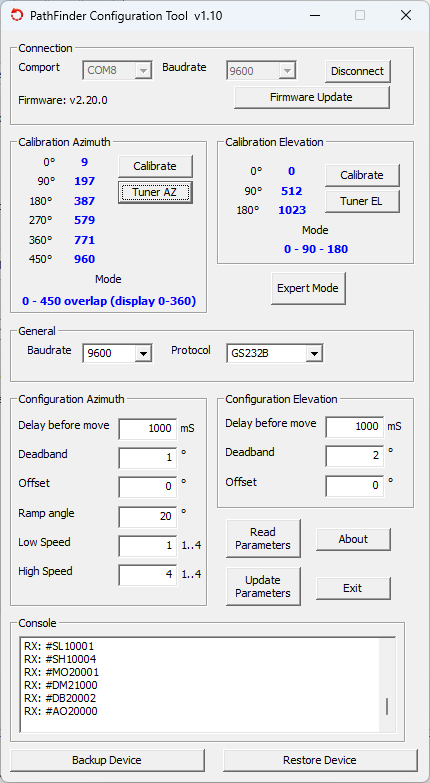
Main window areas
| Area | Description |
|---|---|
| Connection | Select the COM port and click Connect / Disconnect. The firmware version is shown after a successful connection. |
| Calibration Azimuth | Shows the current ADC values for each of the 6 azimuth calibration anchor points (0°–450°). The active mode number is shown next to Mode. Click Calibrate to open the calibration wizard. |
| Calibration Elevation | Shows the current ADC values for the 3 elevation anchor points (0°–180°). Click Calibrate to open the elevation wizard. Expert Mode opens direct ADC editing. |
| General | Sets the GS232 Protocol (A or B) used by tracking software to communicate with PathFinder. |
| Configuration Azimuth | Configures Delay before move, Deadband, Offset, Ramp angle, Low Speed and High Speed for the azimuth axis. |
| Configuration Elevation | Same movement parameters as Azimuth but for the elevation axis. |
| Console | Shows the raw serial communication between the PC and the interface. Useful for diagnostics and verifying commands. |
| Read / Update Parameters | Read Parameters loads the current values from the interface into the UI. Update Parameters writes the displayed values to EEPROM. |
| Backup / Restore | Save all parameters and calibration data to a JSON file or restore from a previously saved file. |
Firmware Update
PathFinder firmware can be updated directly through the application using a
fwv###.fw
firmware file. The application compares versions and requests confirmation before flashing.
Download the firmware file
Download the latest fwv###.fw file from the Downloads page.
Connect the interface
Connect the PathFinder interface via USB and open the PathFinder Configuration Tool. Click Connect.
Open the firmware update dialog
Click Update Firmware in the application. Select the downloaded fwv###.fw file.
Confirm and flash
The application shows the current and new firmware versions. Click Update to confirm. The console shows the flashing progress via avrdude.
Restore parameters
After flashing, restore your backup file via Restore Device to reload all parameters and calibration values.
Backup & Restore
Always make a backup after completing calibration. The backup file contains all parameters and ADC anchor values in JSON format and can be restored in seconds.
Create a backup
Connect to the interface and click Backup Device at the bottom of the main window. Choose a file name and location. The JSON file is saved immediately.
Restore a backup
Connect to the interface, click Restore Device, and select your JSON backup file. All parameters and calibration values are written to EEPROM.
Backup file format
PathFinder
The PathFinder is a compact Windows control panel for day-to-day rotator operation. It connects to the PathFinder hardware interface via Serial (COM port) or TCP (local or remote), shows live AZ and EL compass roses, and can automatically track stations via WSJT-X, JTDX or MSHV.
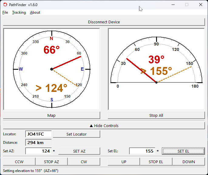
Main window
- Red needle — live position reported by the interface in real time.
- Orange dashed preset (
> X°) — the last target angle sent. - Set AZ / Set EL — type a target angle and click to send a position command.
- CCW / CW / UP / DOWN — continuous movement until STOP is pressed.
- Map button — opens the interactive OSM map with Maidenhead grid overlay.
Settings
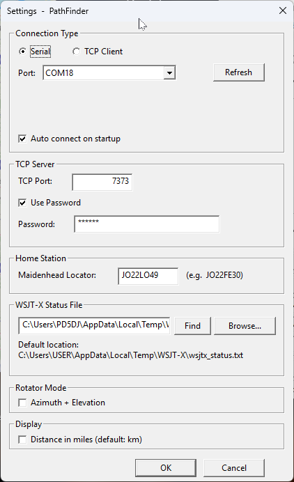
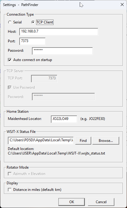
Open Settings via File → Settings.
Connection Type
| Mode | Description |
|---|---|
| Serial | Direct connection via a COM port. Select the port from the dropdown and click Refresh to update the list. |
| TCP Client | Connects outward to a remote PathFinder instance running as TCP Server. Enter host, port (default 7373) and optional password. |
TCP Server
| Field | Description |
|---|---|
| TCP Port | Port the server listens on. Default: 7373. |
| Use Password | Require a password from connecting clients. Recommended for internet access. |
| Password | Password that clients must supply. |
Other settings
| Field | Description |
|---|---|
| Maidenhead Locator | Your home station grid square (e.g. JO22LO). Used for bearing calculations and shown as the home pin on the map. |
| WSJT-X Status File | Path to wsjtx_status.txt. Default: C:\Users\USER\AppData\Local\Temp\WSJT-X\wsjtx_status.txt. |
| Rotator Mode | Enable Azimuth + Elevation to show both compass roses. |
| Display | Show distances in km or miles. |
TCP — Server & Client
PathFinder works both as a TCP Server (accepting incoming connections) and as a TCP Client (connecting outward to a remote instance).
- TCP Server — PathFinder listens on a configurable port (default
7373). The Android app and any GS232-compatible software can connect to it as a client. Enable a password for internet access. - TCP Client — PathFinder connects outward to another PathFinder instance running as TCP Server. Useful when PathFinder runs at the antenna site and you operate remotely over LAN or internet.
- Password — if the remote server requires a password, enter it in the Password field. The connection handshake sends it automatically.
OSM Map — Maidenhead Grid
Click the Map button in the main window to open the interactive OpenStreetMap window with Maidenhead grid overlay.
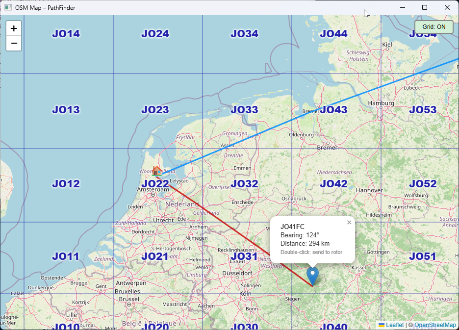
| Element | Description |
|---|---|
| Blue line | Current antenna heading, updated live as the rotor moves. |
| Red line | Great-circle bearing to the last selected locator or WSJT-X station. |
| Grid: ON / OFF | Toggle button that overlays the Maidenhead grid squares. Each square shows its 4-character locator. |
| Locator popup | Click a grid square: shows locator, great-circle bearing (°) and distance (km/miles). |
| Double-click | Sends the bearing directly to the rotator. |
Locator Input
Enter any Maidenhead grid square (4 or 6 characters, e.g. JO33EG) in the Locator field and click Set Locator. PathFinder calculates the bearing from your home locator and fills the Set AZ field.
Click SET AZ to rotate the antenna to the calculated bearing. The orange preset needle in the compass rose updates to > X°.
WSJT-X / JTDX / MSHV Tracking
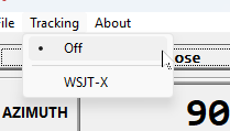
The Tracking menu selects the source that drives the antenna automatically:
- Off — manual control only.
- WSJT-X — PathFinder polls the status file and rotates the antenna whenever a new grid locator appears. Compatible with WSJT-X, JTDX and MSHV.
PathFinder Android Client
The PathFinder Android Client connects to the PathFinder Windows Client via TCP (default port 7373). The PC acts as a bridge between the Android app and the hardware interface. Works on the local network and remotely over the internet, with optional password protection.
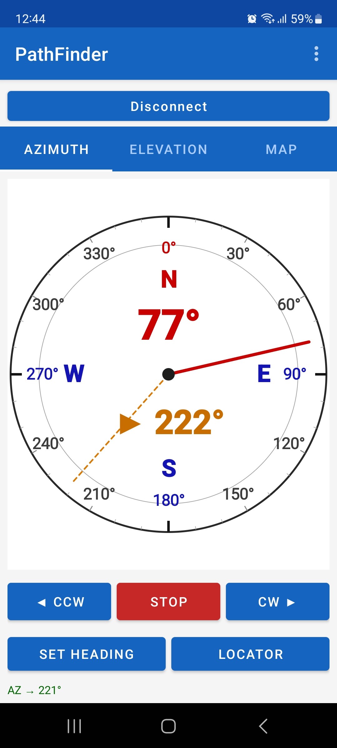
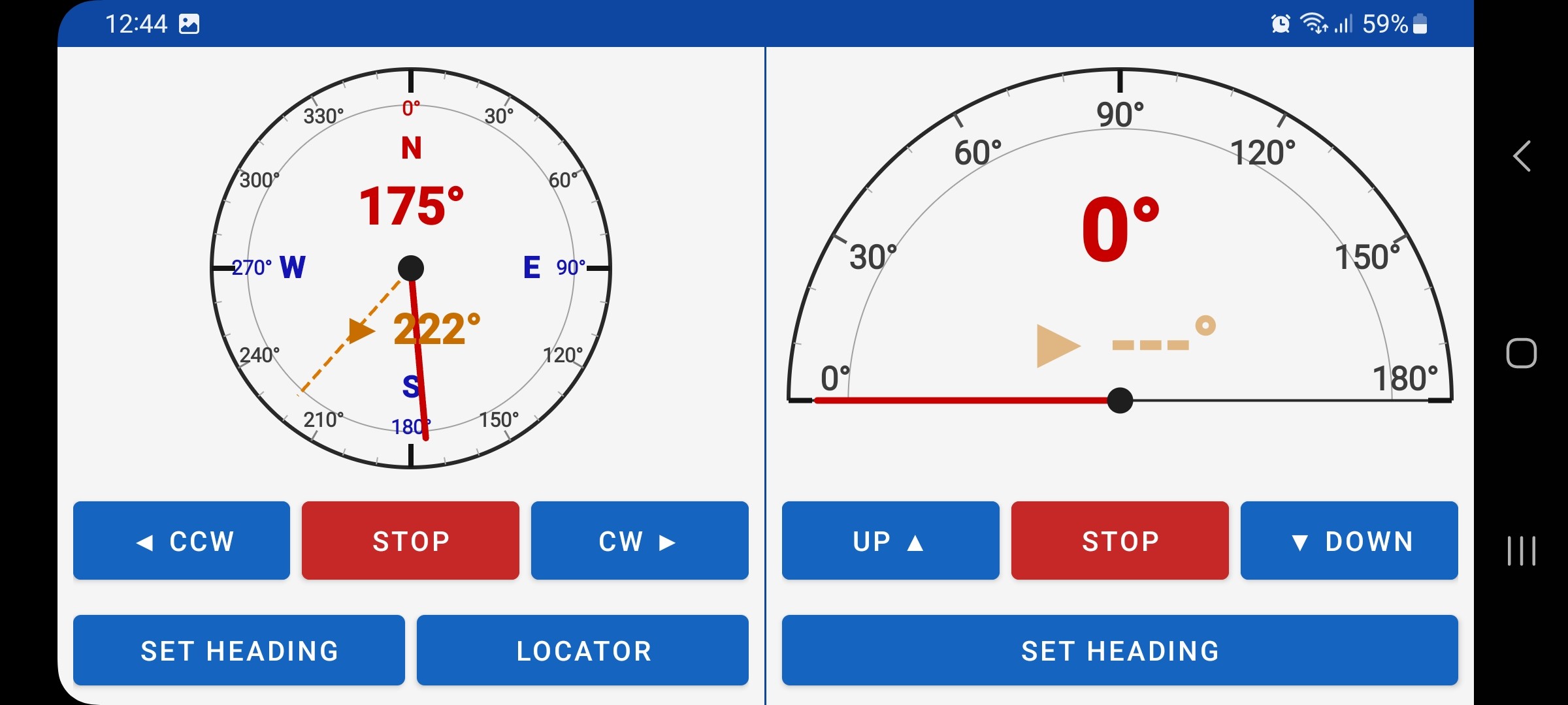
Azimuth Tab
| Element | Description |
|---|---|
| Red needle | Current azimuth position in real time. |
| Orange dashed needle | Target position currently being moved to. |
| Large red number | Current azimuth in degrees. |
| ◀ CCW / STOP / CW ▶ | Continuous movement; STOP halts immediately. |
| AZ field + GO | Type a target azimuth and tap GO to rotate. |
| Locator + Set AZ | Enter a Maidenhead grid square to calculate and fill the bearing automatically. |
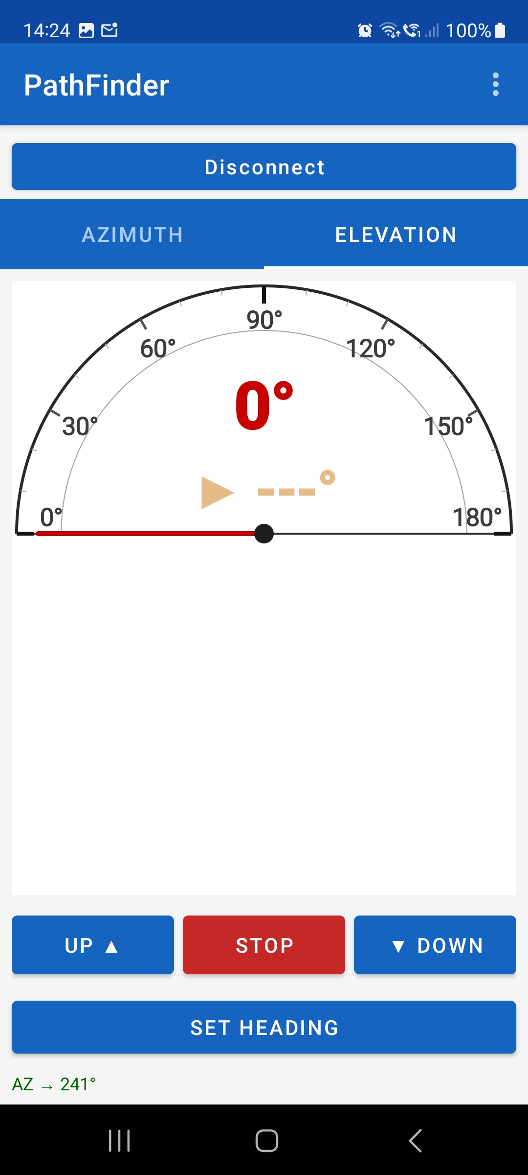
Elevation Tab
| Element | Description |
|---|---|
| Red needle | Current elevation as reported by the interface. |
| Orange dashed needle | Target elevation (shown while moving). |
| UP ▲ / STOP / ▼ DOWN | Continuous movement; STOP halts immediately. |
| EL field + GO | Type a target elevation (0–90° or 0–180°) and tap GO. |
Map Tab
Interactive world map centred on your home station. Tap any point to calculate the great-circle bearing and distance.
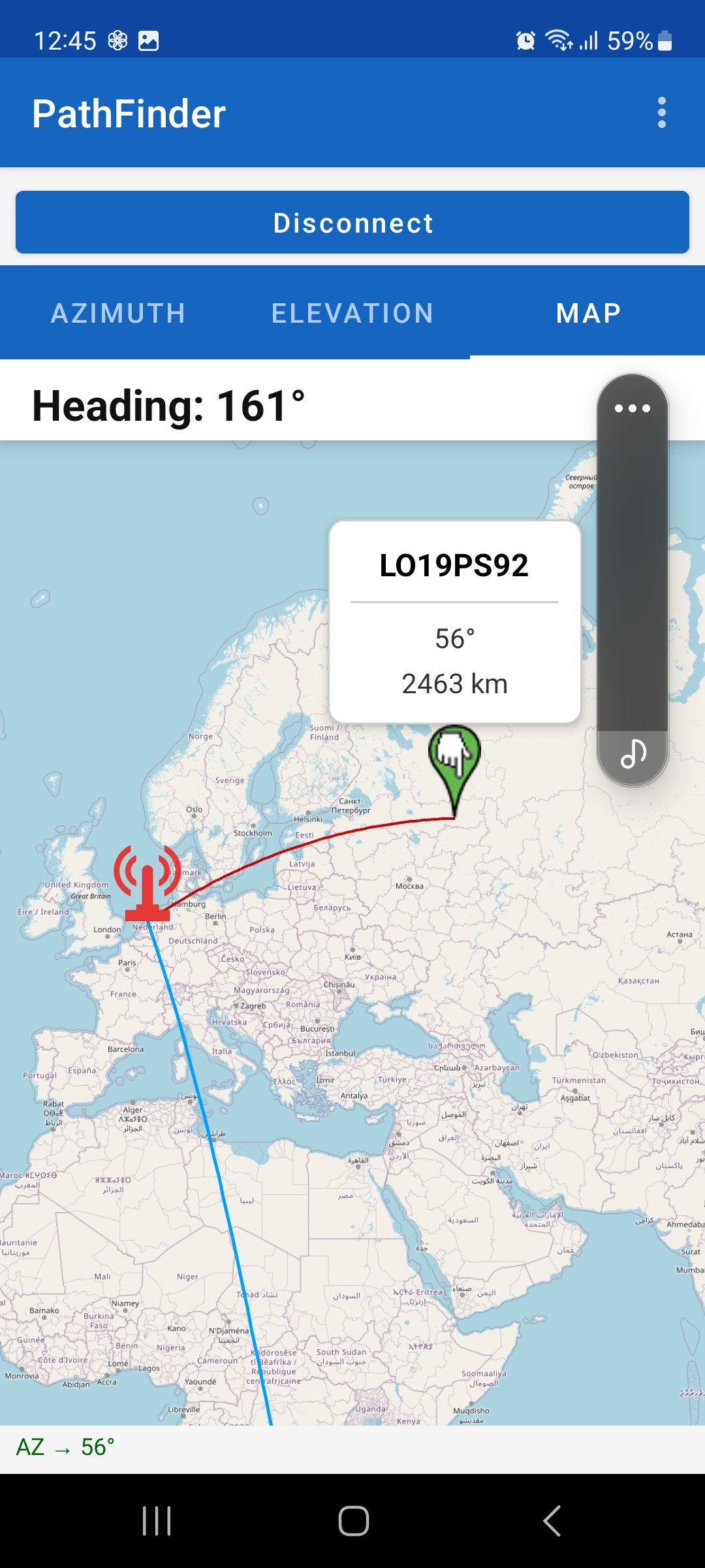
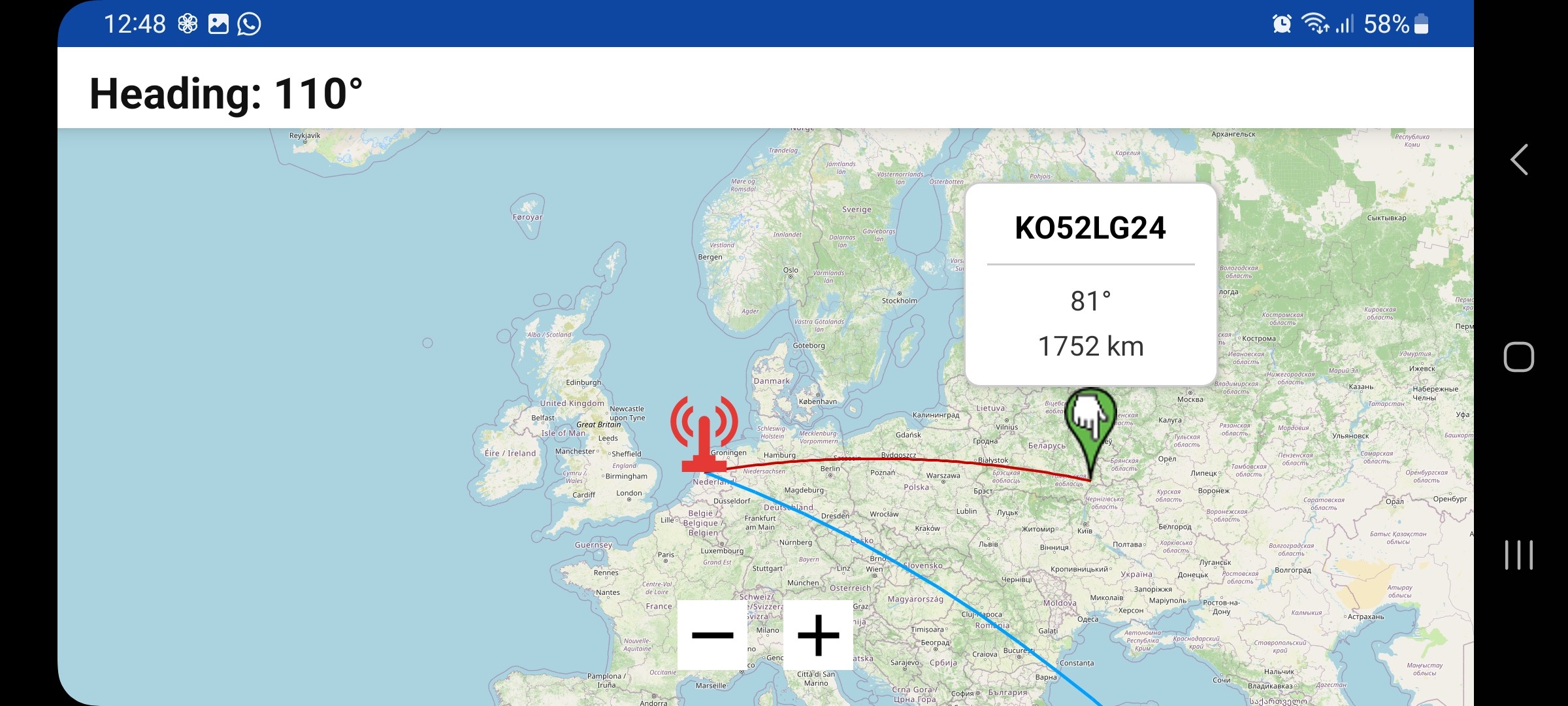
| Element | Description |
|---|---|
| Radio tower icon (red) | Your home station location. |
| Green pin | Tapped location — popup shows grid square, bearing and distance. |
| Red line | Great-circle path from your station to the tapped location. |
| Blue line | Current antenna heading, updated in real time. |
Installation
Download the APK
Download PathFinder_V100.apk from the Downloads page onto your Android device.
Allow installation from unknown sources
Go to Settings → Apps → Special app access → Install unknown apps and allow your browser or file manager.
Install the APK
Open the downloaded PathFinder_V100.apk file and tap Install.
Configure Android Remote in the Windows Client
Open File → Settings, set the TCP Port (default 7373) and optionally enable Use Password.
Connect the Android app
Open PathFinder on your Android device, enter the PC's IP address, port and password, then tap Connect.
192.168.1.10) and port 7373.
7373 on your router to the PC running PathFinder. Enable Use Password and set a strong password to prevent unauthorised access.
Parameters
All parameters are written to the interface's EEPROM via Update Parameters. They persist across power cycles and firmware updates. Click Read Parameters first to load the current values before making changes.
Protocol
GS232A — Legacy format
; Move to AZ 180°, EL 45°
M 180
; Query position
A          → +0180+0045
E          → +0045
S          → +0180+0045
Original Yaesu format. Use with older software that does not support GS232B.
GS232B — Modern format ✓ Recommended
; Move to AZ 180°, EL 45°
W 180 045
; Query position
AL         → AZ=180.0 EL=045.0
SA         → AZ=180.0 EL=045.0
Modern format with clear labels. Supported by all current tracking software.
Selects the GS232 dialect that PathFinder uses to communicate with your tracking or logging software. Both variants are case-insensitive since firmware v2.0.
- GS232B — Use this for all modern software: Orbitron, HRD, N1MM+, Log4OM, Nova, PstRotator. Default and recommended setting.
- GS232A — Only switch to this if your software specifically requires the legacy Yaesu format and does not accept GS232B responses.
AZ / EL Modes
Defines the azimuth operating range. The mode number corresponds to the number of calibration anchor points available and the maximum angle the firmware will report.
| Mode | Range | Anchor points used | Typical rotor |
|---|---|---|---|
| 1 | 0° – 360° | CA1 (0°), CA2 (90°), CA3 (180°), CA4 (270°), CA5 (360°) | G-5400, G-5500 azimuth — no overlap |
| 2 | 0° – 450° | CA1–CA5 + CA6 (450°) | DX(A/C) 800 / 1000 / 2800 — overlap zone |
- DX(A/C) 800, 1000 or 2800 that stays within 360°: use Mode 1 (0–360°).
- DX(A/C) 800, 1000 or 2800 that rotates into the overlap zone (past 360°): use Mode 2 (0–450°). This enables the CA6 anchor at 450°.
Defines the elevation operating range. If your setup has no elevation rotor, set Mode to 0.
| Mode | Range | Anchor points used | Typical use |
|---|---|---|---|
| 0 | Disabled | — | Azimuth-only setup |
| 1 | 0° – 90° | CE1 (0°), CE2 (90°) | Satellite tracking, EME |
| 2 | 0° – 180° | CE1 (0°), CE2 (90°), CE3 (180°) | Over-zenith satellite passes |
- G-5500 for satellite or EME: use Mode 1 (0–90°). Two anchor points are sufficient.
- G-5600B or any rotor that tracks past the zenith: use Mode 2 (0–180°). The CE3 anchor at 180° allows tracking beyond 90° elevation.
- AZ-only setup (no elevation rotor): use Mode 0 to disable EL entirely.
AZ / EL Offset
Shifts all reported azimuth angles by a fixed amount. Use this to compensate for a mechanical alignment error, so that the physical North direction of the rotor reads as 0° in your software.
- Your antenna points to 5° when the rotor reads 0° → set AZ Offset to −5°.
- Your rotor was installed 12° west of North → set AZ Offset to +12°.
- No alignment error → leave at 0° (default).
Same as AZ Offset but for the elevation axis. Compensates for a tilted mast or an imprecisely mounted elevation rotor.
- Rotor reads 3° when antenna is actually at horizon (0°) → set EL Offset to −3°.
- Level mast, no tilt → leave at 0°.
Speed & Ramp Angle
The DAC speed level used at the start of a movement and during the deceleration ramp before reaching the target. Level 1 = lowest voltage to the rotor motor; Level 4 = highest.
- Level 1 (recommended default) — gentlest start/stop, maximises motor and gearbox life.
- Level 2 — slight increase in starting torque, useful in cold climates where grease thickens.
- Do not set Low Speed higher than High Speed.
The DAC speed level used during the main part of the travel — between the ramp-up at the start and the ramp-down before the target. Higher levels rotate the rotor faster.
- Level 4 — maximum speed, shortest rotation time. Suitable for most setups.
- Level 3 — 25% slower. Use if your rotor clock gets warm at level 4, or to reduce mechanical stress on large antennas.
- Level 2 — half speed. Useful for very large, heavy antenna arrays.
The angular distance before the target at which PathFinder begins reducing speed from High Speed to Low Speed. A larger ramp angle gives a softer, more controlled stop.
- 20° (default) — suitable for most rotors. Deceleration begins 20° before target.
- 30° — very soft landing, good for heavy antenna arrays with high inertia.
- 10° — sharper stop, useful when you need the fastest possible tracking response.
- 0° — no ramp, rotor runs at full speed until it reaches the deadband. Not recommended for mechanical longevity.
Deadband
The rotor stops as soon as its measured position is within the deadband of the target angle. A wider deadband prevents hunting (continuous small corrections back and forth).
- 2° (default EL) — good general setting. The rotor stops within ±2° of target.
- 0° — maximum precision. Only use this if your rotor and potentiometer are very stable and free of mechanical backlash.
- 5° — relaxed deadband. Use for wide-beam antennas where pointing precision is less critical.
Movement Delay
When the rotor must reverse direction (e.g. from CW to CCW), PathFinder waits this many milliseconds after switching off the current direction before starting the new direction. This protects the relay contacts and the rotor motor from voltage spikes caused by simultaneous switching.
- 1000 ms (default) — 1 second pause on direction change. Conservative and safe for all rotor types.
- 100 – 500 ms — suitable for lightweight satellite antennas. Reduces wait time during rapid passes.
- 2000 ms — use for large, heavy antenna systems or older rotor clocks with mechanical relays that need more time to fully open before reversing.
- 0 ms — no delay. Only for direct solid-state drive circuits without relay contacts.
Typical Setup Scenarios
Recommended parameter values for the most common configurations.
Scenario 1 — AZ-only, 0–360° (DX 800/1000 + G-5400)
| Parameter | Recommended value | Reason |
|---|---|---|
| Protocol | GS232B | Modern software compatibility |
| AZ Mode | 1 (0–360°) | Single-revolution rotor |
| EL Mode | 0 (disabled) | No elevation rotor |
| AZ Offset | 0° | Align mechanically during installation |
| Low Speed | 1 | Gentle start/stop |
| High Speed | 4 | Maximum travel speed |
| Ramp Angle | 20° | Default, smooth stop |
| Deadband AZ | 2° | Good precision without hunting |
| Delay AZ | 1000 ms | Relay protection |
| Calibration | 5 points: 0°, 90°, 180°, 270°, 360° | Full range coverage |
Scenario 2 — AZ-only, 0–450° (DX 2800 + G-2800)
| Parameter | Recommended value | Reason |
|---|---|---|
| AZ Mode | 2 (0–450°) | Extended overlap zone |
| EL Mode | 0 (disabled) | No elevation rotor |
| Ramp Angle | 25° | G-2800 has more inertia — longer ramp |
| High Speed | 3 | Reduce stress on heavy array |
| Deadband AZ | 3° | Prevents hunting with heavy load |
| Calibration | 6 points: 0°, 90°, 180°, 270°, 360°, 450° | Covers the full overlap range |
Scenario 3 — AZ + EL satellite tracking (G-5500)
| Parameter | Recommended value | Reason |
|---|---|---|
| Protocol | GS232B | Required by Orbitron, Nova, MacDoppler |
| AZ Mode | 1 (0–360°) | G-5500 azimuth is single-revolution |
| EL Mode | 1 (0–90°) | Standard LEO elevation |
| Deadband AZ | 2° | Good satellite tracking accuracy |
| Deadband EL | 2° | Good satellite tracking accuracy |
| Delay AZ | 500 ms | Faster response for low-horizon passes |
| Delay EL | 500 ms | Quick elevation reversal needed |
| AZ Calibration | 5 points: 0°, 90°, 180°, 270°, 360° | Full azimuth |
| EL Calibration | 2 points: 0°, 90° | Standard elevation |
Scenario 4 — EME (AZ + EL, 0–180° elevation)
| Parameter | Recommended value | Reason |
|---|---|---|
| Protocol | GS232B | Required by moon-tracking software |
| AZ Mode | 1 (0–360°) | Standard azimuth |
| EL Mode | 2 (0–180°) | Over-zenith capability for moon path |
| Deadband EL | 1° | EME requires precise pointing |
| Ramp Angle AZ | 20° | Standard |
| EL Calibration | 3 points: 0°, 90°, 180° | Full over-zenith range |
Serial Commands Reference
PathFinder uses four command prefixes over the serial port. All commands are
case-insensitive (since firmware v2.0) and terminated with
\r or
\n.
Commands and responses are visible in real time in the Console pane of the PathFinder application.
#xxx response.<<OK>> or error.? read command.GS232 Motion Commands
| Command | Syntax | Description | Response (GS232A / GS232B) |
|---|---|---|---|
C | C | Query current azimuth position. | +0180 / AZ=180 |
B | B | Query current elevation position. | +0045 / EL=045 |
C2 | C2 | Query azimuth and elevation in one response. | +0180+0045 / AZ=180 EL=045 |
M | M<az> | Move azimuth to target angle. | — (error if out of range) |
W | W<az> <el> | Move azimuth and elevation simultaneously. | — (error if out of range) |
R | R | Start continuous CW azimuth rotation. | — |
L | L | Start continuous CCW azimuth rotation. | — |
A | A | Stop azimuth movement. | — |
U | U | Start continuous UP elevation movement. | — |
D | D | Start continuous DOWN elevation movement. | — |
E | E | Stop elevation movement. | — |
S | S | Stop all movement — azimuth and elevation. | — |
? Read Commands (parameter readback)
| Command | Response example | Description |
|---|---|---|
?FMW | #FMW0130 | Firmware version string. |
?PRO | #PRO0001 | Protocol: 0 = GS232A, 1 = GS232B. |
?MO1 | #MO10001 | Azimuth mode: 1 = 0–360°, 2 = 0–450°. |
?MO2 | #MO20001 | Elevation mode: 0 = disabled, 1 = 0–90°, 2 = 0–180°. |
?DM1 | #DM11000 | Delay before move — azimuth (ms). |
?DM2 | #DM21000 | Delay before move — elevation (ms). |
?DB1 | #DB10002 | Deadband — azimuth (°). |
?DB2 | #DB20002 | Deadband — elevation (°). |
?AO1 | #AO10000 | Offset — azimuth (°). |
?AO2 | #AO20000 | Offset — elevation (°). |
?SA1 | #SA10020 | Ramp angle (°). |
?SL1 | #SL10001 | Low speed (DAC level). |
?SH1 | #SH10004 | High speed (DAC level). |
?CA1–?CA6 | #CA10009 | AZ calibration ADC values at 0°–450°. |
?CE1–?CE3 | #CE10000 | EL calibration ADC values at 0°–180°. |
$ Write Commands (configuration)
Format: $XXXvalue — no space between code and value.
On success: <<OK>>.
On range error: ERROR XXX RANGE ....
| Command | Example | Description |
|---|---|---|
$PRO | $PRO1 | Set protocol: 0 = GS232A, 1 = GS232B. |
$MO1 | $MO11 | Set azimuth mode (1 or 2). |
$MO2 | $MO20 | Set elevation mode (0, 1 or 2). |
$DM1 | $DM11000 | Set delay before move — azimuth (ms). |
$DM2 | $DM21000 | Set delay before move — elevation (ms). |
$DB1 | $DB12 | Set deadband — azimuth (°). |
$DB2 | $DB22 | Set deadband — elevation (°). |
$AO1 | $AO1-005 | Set offset — azimuth (°). Negative values supported. |
$AO2 | $AO20 | Set offset — elevation (°). |
$SA1 | $SA120 | Set ramp angle (°). |
$SL1 | $SL11 | Set low speed (1–4). |
$SH1 | $SH14 | Set high speed (1–4). |
$CA1–$CA6 | $CA1 | Live-capture AZ calibration anchor (current ADC value). |
$CE1–$CE3 | $CE1 | Live-capture EL calibration anchor (current ADC value). |
$AA1–$AA6 | $AA10009 | Directly set AZ ADC anchor value (Expert mode). |
$AE1–$AE3 | $AE10000 | Directly set EL ADC anchor value (Expert mode). |
Expert ADC Calibration
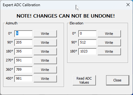
Click Expert Mode in the Calibration Elevation group in the main window to open this dialog. It shows all 9 calibration points (6 azimuth + 3 elevation) and lets you read and write each point individually to EEPROM.
| Field | Axis | Angle | ADC range |
|---|---|---|---|
| 0° (AZ) | Azimuth | 0° | 0 – 1023 |
| 90° (AZ) | Azimuth | 90° | must be > 0° value |
| 180° (AZ) | Azimuth | 180° | must be > 90° value |
| 270° (AZ) | Azimuth | 270° | must be > 180° value |
| 360° (AZ) | Azimuth | 360° | must be > 270° value |
| 450° (AZ) | Azimuth | 450° | must be > 360° value (Mode 2 only) |
| 0° (EL) | Elevation | 0° | 0 – 1023 |
| 90° (EL) | Elevation | 90° | must be > 0° value |
| 180° (EL) | Elevation | 180° | must be > 90° value (Mode 2 only) |
Use Read ADC Values to load the current EEPROM contents into all fields before editing. After changing a value, click the individual Write button next to that field to save only that value. Click Close when done.
- → After a firmware re-flash that reset the EEPROM: restore individual values from your JSON backup without running the full wizard.
- → Fine-tuning a single anchor point that has drifted slightly after a potentiometer replacement.
- → Restoring from a backup when the Restore Device button is unavailable (e.g. a different firmware version).
Tips & Troubleshooting
C (query azimuth) or C2 (query azimuth + elevation) and compare the reported angle against a known physical bearing. For a consistent offset, use the AZ Offset parameter to correct it.
Write Mode
Write Mode is a standalone function, separate from calibration. It saves the currently selected calibration mode (e.g. 3-point or 6-point) to EEPROM without running a new calibration.
Only use Write Mode when you want to change the active calibration mode (for example from 3-point to 6-point) without repeating the full calibration procedure. Open the calibration dialog, select the desired mode, and click Write Mode.
GS232 — The Standard Protocol
PathFinder exposes a standard GS232 serial interface over USB. Your logging, tracking or satellite software simply connects to the assigned COM port, selects GS232A or GS232B, and starts sending position commands. No special drivers or adapters are needed. PathFinder supports both GS232A and GS232B — switch in the Parameters settings.
GS232A — Legacy format
M 180
A  → +0180+0045
Original Yaesu format. Use with older software that does not support GS232B.
GS232AGS232B — Modern format ✓ Recommended
W 180 045
AL  → AZ=180.0 EL=045.0
Modern format with clear labels. Supported by all current tracking and logging software.
GS232B RecommendedCompatible Applications
All software that supports GS232A or GS232B works directly with PathFinder.
Orbitron
Popular freeware satellite tracker for Windows with a GS232 rotator plug-in. Drives AZ+EL automatically based on TLE calculations.
GS232A/BSatelliteAZ+ELMacDoppler / WXtrack
Professional satellite tracking software. Drives AZ+EL automatically based on real-time TLE calculations and Doppler correction.
GS232BSatelliteNova for Windows
Professional satellite and moon tracking software with GS232 AZ+EL support. Ideal for EME (moonbounce) operation.
GS232BSatelliteEMEHam Radio Deluxe
HRD Rotator module supports GS232B and can drive the rotor directly from the logbook based on the worked DX entity.
GS232BLoggingN1MM+ Logger
Contest logger with built-in GS232 rotator support. Automatically points the antenna at the DX station while logging.
GS232A/BContestLog4OM
Full-featured logging program with GS232 rotator integration. Auto-points the antenna based on the worked DXCC entity.
GS232BLoggingPstRotatorAz
Dedicated rotator controller software with extensive GS232 support and map display. Popular for VHF/UHF contest operation.
GS232A/BRotator controlAny GS232-compatible software
If your software supports GS232A or GS232B rotator control, it works with PathFinder. Just set the correct COM port and protocol.
GS232AGS232BSetting Up Your Software
Three steps to connect any GS232-compatible software to PathFinder.
Find the COM port
Open Windows Device Manager and look under Ports (COM & LPT). The PathFinder interface appears as USB Serial Port (COMx) where x is the assigned number, e.g. COM7.
Set protocol and baud rate
In your software, select rotor type GS232B (recommended) or GS232A. Set the baud rate to 9600 bps. No flow control needed.
Connect and test
Select the correct COM port and click Connect. Send a position query (e.g. C or C2) to verify the connection. The PathFinder console pane shows all communication in real time.
AZ=180.0 EL=045.0) that are easier to verify and debug. Only switch to GS232A if your software specifically requires the legacy format.